|

DETERMINING POSITION |
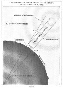
“Where am I?” seems an easy question with today’s technology so we may soon forget the struggle man has gone through to answer that question. The geographic answer to that question here on earth is now answered in degrees of latitude and longitude on the earth’s surface and one’s elevation above the sea. To get to that answer takes you on a 2,200 year journey from computing the size of the Earth, through using time to navigate ships and navigating airplanes by radio waves, to differential GPS. Here’s how we got where we are today. First it was necessary for us to determine that we live on the surface of a globe (an oblate spheroid actually). Though that was debated for at least two thousand years, some early Greeks put a stake in the ground for that “position”. Eratosthenes (~200 BC) famously went so far as to calculate the circumference of our globe as depicted in the graphic to the right – and he made a reasonably good estimate.
A few years later, the great Greek astronomer, Hipparchus, used a convention like latitude and longitude on the surface of our sphere to specify locations. He measured latitude by the sun’s altitude at its daily peak and proposed that longitude be measured using time recognizing the Earth’s rotation. Thus the basis for the 2D answer to the question "Where am I" was proposed over two thousand years ago. Claudius Ptolemy (~150 AD) applied these concepts and developed a coordinate system for mapping the known (largely Roman) world of his day in his masterpiece, Geographia. He devised a coordinate system with latitude starting at the equator and 180° longitude starting at the Cape Verde Islands and spanning to mid- China. The atlas provided the locations of major cities and landmarks.
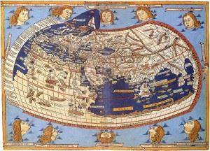
Renaissance cartographers resurrected Ptolemy's data and recreated his remarkable world view such as the example to the right. His latitude measures were based on the number of daylight hours for the longest day in the year and were for some locations in error by a few degrees. [The longest day ranges from 12 hours at the equator to 24 hours at the pole.] His contemporary astronomers had latitudes for many locations accurate to less than a degree. So the latitude part of the position question was largely solved for land sites by Ptolemy's time of ~150AD. Ptolemy chose to use an estimate of ~18,000 miles for the earth’s circumference though he had used larger estimates in his earlier work. This lead to a substantial error in his longitude measures, a problem that plagued western cartographers and explorers until the Age of the Discovery finally established a better estimate. He presciently recognized that the best longitude measures would require simultaneous astronomical observations to determine the relative east-west positions on our rotating globe.
The great Indian mathematician and astronomer, Aryabhata (~500 AD), also theorized that the earth rotated on its axis and accurately measured the time of rotation. Following the works of the Muslim scholars in the 800s and his own genius, the Persian, al-Birini (~1000 AD), accurately estimated the earth’s dimensions. By instituting triangulation in his measurements, he provided accurate coordinates and distances between of hundreds of locations in the Middle East and parts of India. Unknown to the West, but widely known in the Muslim World, this solution to longitude on land had to be "rediscovered" five hundred years later in Europe. The ultimate solution for longitude, its accurate measure at sea where triangulation and reliable astronomical measurements were impossible, had to wait for the invention of the chronometer in the late 1700s. The British had suffered great losses of ships at sea due to errors in navigation and they established the Board of Longitude in 1714 and Longitude Prize for the solution. Spain and France had sponsored similar competitions. Over the ensuing decades several approaches famously competed including the relative positions of Jupiter’s moons, the lunar distance method, and marine chronometers, the dark horse in the race. Harrison’s chronometers ultimately won but the lunar distance method survived until the early twentieth century as a less expensive solution. Somewhat in parallel with these macroscopic developments based on astronomical observations, the science of surveying developed from the Egyptian and Roman times. Possibly the greatest advancements were made a thousand years ago during the Caliphate by the Muslim mathematicians and practitioners. They invented techniques to level their instruments and the alidade and astrolabe for measuring angles. Distance continued to be measured by lengths of chain or rope. If one new the position of one point on the Earth, one could accurately define the position of another point through the by using the geometry of triangles – triangulation.
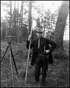
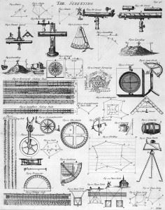
Triangulation not only enables calculating an accurate horizontal position (i.e. latitude and longitude), it can be used in the third dimension to calculate elevation. Thus the third part of our question can be answered – at least the relative elevation to a point on lower ground. By the late 1500s the telescope was applied to surveying through the invention of the theodolite which measures both horizontal and vertical angles. By the 1700s the practice of surveying was broadly established and with a wide range of tools as depicted to the right.
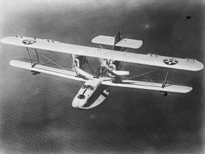
With these tools large scale mapping was undertaken in 1700 and 1800s. Long arcs of land were accurately surveyed stretching from points at the sea inland – and thus elevations from sea level could be established. So the static problem position problem was solved by the late 1700s and the world was accurately mapped by the early twentieth century. THE REAL TIME PROBLEMA new question arose however with the increasingly rapid transportation provided by the flying machine: “Where am I and where will I be?” given I am moving at 100+ mph through the air. The somewhat sedate nautical navigation solution using sextants, tables, and charts was tried but proved inadequate. One needed to know the answer quickly and with minimal, ideally no, calculations. Fortunately new science and technology answered the question just in time.
The development of electromagnetic theory and radio technology in the early twentieth century provided the means to chart your course in the air. First plots relied upon simple radio direction finders – radios with directionally tuned antennas to locate the direction toward a radio transmitter. The crossing of two of these vectors can provide a very crude estimation of position. The onboard barometer, the altimeter gives the elevation, altitude. Sophistication grew rapidly in the 30s and especially in WWII with the advent of radar and related technologies. Acronym soup also began with system names such as LFF, LFR, GEE, TACAN, DECCA, OMEGA, DME and VOR. Aside from using the radio beam direction, they may measure distance by signal travel times (like radar), and velocity by Doppler effects. LORAN, Long Range Aid to Navigation, calculates location by assessing the difference in arrival times for radio pulses carefully controlled from multiple radio transmitters. Though LORAN became popular later in the twentieth century, the DoHS (Dept. of Homeland Security) shut down the transmitters on February 8, 2010 in favor of the current GPS based solutions. Of all of these systems, only VOR and DME remain in significant use today. VOR (VHF Omni directional Range) provides an inexpensive radial angle to the transmitter and can demark an airway route through phase differences between two transmitted signals. A DME (Distance measuring equipment) transmitter is often collocated with a VOR to provide the range to the transmitter by the time delay in sending a message from the aircraft and receiving a corresponding reply to the DME station. These systems can be augmented with GPS or inertial guidance systems.Inertial Navigation Systems (INS) were first put into operation for the Atlas ballistic missile first built in San Diego in the 60s. Essentially a dead-reckoning system, an INS uses a set of gyroscopes to measure the movement of the vehicle very precisely and can measure altitude as well as Lat/Long. They are still in use on submarines and commercial aircraft in conjunction with the GPS, VOR, and DME to provide the best estimate of position aboard an aircraft. With the advent of cell phones and networks, the location of the phone can be determined by its proximity to the cell towers in its neighborhood. The best of these methods employ three nearby cell towers to use trilateration of their signals and the phone to estimate position to a circle about 1 mile in diameter. By 2006 all new cell phones in the US had to provide a means to locate the phone in an emergency and the use of GPS has become the preferred solution. SATELLITE SOLUTIONS
With the launch of the first satellites in the 50s and 60s, engineers began to scheme to find ways to apply them to the position and navigation problem. The first systems were successfully tested by the US Navy in the 60s leading to proof of concept tests for the Global Positioning System (GPS) in the early 70s. The first GPS satellite was launched in 1978 but the full system with all 24 satellites did not become fully operational until 1995.In the intervening years, Qualcomm of San Diego developed and implemented a proprietary satellite based location and messaging system called OmniTRACS in 1985. Used to track trucks and trailers, nearly one million units are in operation for commercial and military uses today. Military usage for navigating and targeting had precedence initially so commercial users could only receive a degraded signal which provided a much less accurate position estimate. In 2000 this distinction was removed and all users began using the most accurate signals. As of the end of 2009, 58 GPS satellites had been launched and 30 were still in operation. The GPS receiver determines its position by calculating its distance to at least 3 and much preferably 4 GPS satellites. Each satellite sends a signal containing its exact location, the time the signal was sent, and some other status data. To measure the radial distance to the satellite, the receiver records the time of arrival for each satellites’ signal and, compared to the signal’s message time, the transit time for each. Given the transit time for each message which travels at the speed of light, the distance from the each satellite’s location is readily computed. Each distance is the radius of a sphere and the intersection of all 4 of the calculated spheres from the 4 satellites represents the receiver’s position – latitude, longitude, and altitude – and time as well! The space segment of the system encompasses about 30 GPS satellites in orbits about 12,000 miles above Earth so that each circles the globe twice per day. At any one time, typically 8 are visible from a spot on the ground. The Control segment is comprised of over a dozen world-wide facilities for tracking and control. The entire system is managed by the USAF 50th Space Wing in Los Angeles. Though GPS has been a US development for decades, several competitors are coming on-line over the next few years:
In addition to these future systems, a number of regional or national specialized systems to augment GPS are under development. THE CURRENT STATE OF AFFAIRSAs mentioned before, INS, VOR, DME and GPS are frequently integrated in the flight management systems of commercial aircraft to improve position accuracy. Still greater accuracies are desired for surveying, mapping, GIS and aerial remote sensing as well as air navigation. Many enhancements are based on using differential GPS which is being implemented to address all these applications. Here’s the status:
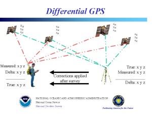
A differential GPS improves accuracy of GPS measurements by estimating the error in the receiver’s GPS position measurement. A second GPS receiver placed at precisely known geographic position is used as a reference or standard. The error it calculates between its GPS measured position and its true position is used to adjust the surveyor’s GPS measured position. This error correction can be done later such as by post processing survey data back at the lab. It can also be done in real time as depicted below by continuously transmitting the reference’s error (“delta”) to the surveyor’s GPS. This basic approach can be applied to real time remote sensing in aerial surveys enabling, for example, each pixel of a digital aerial photograph of the Earth to be geo-referenced as the photo is taken during flight. The direct integration into a GIS can be accomplished virtually immediately. Alternative systems can supplement this GPS data with LiDAR (Light Detection And Ranging using a laser system) topographic data to refine the remote sensing accuracy even further.
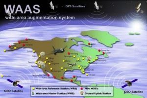
WAAS, the last system listed above in the table, is a differential GPS system too but on a global scale. It is being implemented by the FAA to enable aircraft to rely on GPS for all phases of flight, including precision approaches to any airport that it covers. The Wide-area Reference Stations (WRS) are precisely located and transmit the GPS data they receive to the Wide-area Master Stations (WMS) that calculate the position errors which are transmitted to the Ground Uplink Stations (GUS). The GUS sends the error correction data to the satellites for rebroadcast to the using aircraft. Much of the system is in operational test and evaluation at this time. So we’ve come a long way to get to know where we are right now. What would Eratosthenes think of all this? |
|

%20satellite.jpg)